The National Fire Protection Association (NFPA) 70B standard sets forth standards for “Electrical Equipment Maintenance”. In its 2023 edition, chapter 9 of NFPA 70B transitions from a “Recommended Practice” to a more structured “Standard” with a heightened emphasis on mandatory compliance. However, unlike the National Electric Code (NEC), which is adopted by states as law, NFPA 70B is not directly mandated by law and should be regarded as a foundational guideline for ensuring electrical safety.
NFPA 70B aims to establish an Electrical Maintenance Program geared towards enhancing safety and reliability. The 2023 edition of NFPA 70B introduces new classifications for physical conditions of equipment (referred to as Levels 1, 2, and 3), which dictate the frequency of maintenance, ranging from 6 to 60 month intervals, contingent upon the product category.
When conducting maintenance, it is always advisable to adhere closely to the recommendations and instructions provided by equipment manufacturers, as this represents a best practice approach to ensure optimal performance and safety.
How does ESL’s equipment help comply with NFPA 70B?
When using portable generators in conjunction with an ESL StormSwitch®, TripleSwitch®, DualConnect™, or RotaryConnect™ system, it’s essential to ensure seamless operation. To do so, first disconnect the portable generator from the ESL unit. Then, connect a portable load bank to the portable generator in accordance with the generator manufacturer’s recommended maintenance instructions. This ensures efficient and reliable performance of the generator. For permanent generators integrated with an ESL TripleSwitch® or DualConnect™ system, a similar approach applies. In this case, simply connect a portable load bank to the output CAMs on the ESL unit, adhering closely to the generator manufacturer’s maintenance guidelines. This step facilitates optimal functioning and longevity of the generator setup within the ESL system.
To contact ESL for additional questions or a quote, click here.
Adding a generator docking station to a new or existing facility is a useful solution which requires careful planning to ensure a successful and safe installation.
Learning Objectives
Understand the differences between different docking station configurations.
Learn special considerations for emergency and service entrance docking station installations.
Understand what accessories should be specified for different docking station installations.
Generator Insights
Generator docking stations can be used for backup power systems.
There are many considerations when specifying these generator docking stations. Depending on the application and if a permanent generator is included, this may include a portable load bank connection.
Generators have become commonplace as a piece of facility infrastructure to support critical building loads. Though these backup power systems are often reliable, they are not perfect. Permanent backup power systems can become unavailable due to planned outages for maintenance or unplanned outages due to component failure.
Engineers must plan for these contingencies, as well as provide systems that comply with the latest NFPA 70: National Electrical Code requirements. One product that is becoming increasingly common as a solution is the generator docking station.
A consistent trend has emerged in modern commercial and industrial power system design: The desire for increased resilience for critical systems. Resilience can be defined as “the capacity to recover quickly from difficulties.” In the context of power systems, it is no surprise the desire to recover quickly from a difficulty such as an unexpected power outage is in high demand.
This increased demand for more resilient power systems has taken on many forms and has resulted in many different project types for consulting engineers to design. Some examples of the project types are:
Generator and transfer switch replacements.
Generator plant upgrades with Day One paralleling or future paralleling.
Redundant utility services.
Generator docking stations (retrofits for existing facilities and new builds).
Portable Generator and Manual transfer switch additions.
Portable Load Bank Connection and Portable Generator Connection for existing Permanent Generators.
Generator docking stations are interesting because of their increasing prevalence in new and existing buildings. Docking stations are not new, but they have significantly evolved from the docking stations of the past.
NEC code requirements
We have seen a significant uptick in the demand for generator docking stations because of this desire for increased resiliency, but also because of new code requirements in NEC. In the 2017 edition of NEC, section 700.3(F) was added to the “Emergency Systems” article. This new section, titled “Temporary Source of Power for Maintenance or Repair of the Alternate Power Source,” requires that emergency systems with a single generator “Include permanent switching means to connect a portable or temporary alternate source of power, which shall be available for the duration of the maintenance or repair.”
This code section also has four exceptions which would permit the omission of this permanent switching means:
Exception No. 1: “All processes that rely on the emergency system source are capable of being disabled during maintenance or repair of the emergency source of power.” This exception allows the temporary source to be omitted if the emergency loads can be switched off. This may not be practical for some applications where emergency systems such as fire alarm and egress lighting cannot be disabled.
Exception No. 2: “The building or structure is unoccupied and fire protection systems are fully functional and do not require an alternate power source.” It is difficult to see how one could be confident that a building would be unoccupied during the time that an emergency generator would need to be repaired, though there may be some building types where this exception could be applied. Buildings with fire pumps that are required to have an alternate power source would not be permitted to utilize this exception.
Exception No. 3: “Other temporary means can be substituted for the emergency system.” It is not clear what temporary means would be permitted to qualify for this exception; therefore this would need to be determined by the authority having jurisdiction.
Exception No. 4: “A permanent alternate emergency source, such as, but not limited to, a second on-site standby generator or separate electric utility service connection, capable of supporting the emergency system, exists.” This exception allows paralleled generator systems to be excluded from this code requirement as well as a separate utility service.
While it may be tempting for engineers to fall back on these exceptions to reduce the upfront electrical system cost, it is advisable to discuss the pros and cons of having a generator docking station with the owner. The owner may prefer to install the docking station despite the additional cost to increase reliability and reduce any possible liability should the permanent emergency system experience a failure.
Another requirement of section 700.3(F) is that temporary source switching means contain a contact for indicating the permanent emergency power source is disconnected. This signal must be annunciated at a location remote from the generator or at another facility monitoring system. This is a critical monitoring component that should not be overlooked by engineers and inspectors alike. Successful implementation of this code requirement will ensure the switching means is less likely to be left in the wrong position during the transition back from the temporary to the permanent emergency power source.
Two docking station configurations
There are a few ways where a docking station can be configured to allow a temporary generator to provide power to the permanently installed emergency electrical system.
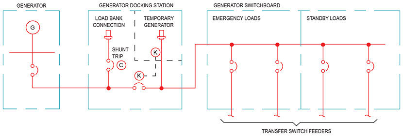
Common load bus configuration: The first way a docking station can be introduced into an electrical system is by connecting the load side of the docking station to the load side of the generator. In a practical application, this can be accomplished by providing a single feeder from the distribution point for the generator, which may be a panelboard or switchboard (Figure 1). This solution is ideal for retrofit applications, where the generator and emergency distribution system equipment are already installed. This configuration can also be ideal for site configurations where the docking station location is not near the permanent generator location. To comply with NEC 700.3(F), a mechanical or electrical interlock must be installed to prevent the inadvertent connection of two power sources. The simplest way to provide this interlock is with a mechanical key type locking mechanism, which is configured to require the generator circuit breaker to be in the open position before the temporary generator connectors can be accessed.
Figure 1: The common load bus configuration connects the docking station directly to a generator distribution panelboard.
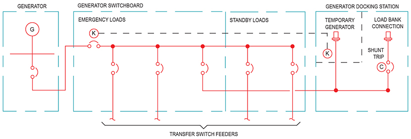
In-line configuration: For this configuration, the docking station is placed between the generator and the distribution equipment (Figure 2). One advantage of this configuration over the common load bus is it does not require a separate feeder from the distribution equipment, providing reduced material and labor costs. This configuration is ideal for situations where the docking station can be placed near the permanent generator location.
Figure 2: The in-line configuration places the docking station between the generator and the generator distribution panelboard.
Particular attention should be paid to the quantity and location of circuit breakers, which are integral to the docking station, as well as the point the permanent generator conductors are terminated. In some single circuit breaker configurations, the conductors on the load side of the permanent generator circuit breaker remain energized when the temporary generator is connected. This creates a potentially dangerous situation, especially if the generator is undergoing maintenance and the technicians are not aware of this condition. The recommended solution is to specify a docking station circuit breaker configuration that fully isolates the generator conductors from the temporary generator source.
Load bank considerations
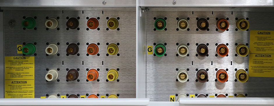
When a generator docking station is installed, a piece of equipment, which is permanently wired to the emergency power distribution equipment is now accessible at the exterior of the building. For project applications that warrant the frequent use of portable load banks, this presents a great opportunity to make load bank hook-ups quick and efficient. Docking stations are available in configurations designed for load banks only, but it is likely the design engineer or facility owner will also want the capability of connecting a temporary generator. In this situation, it is recommended a dual-purpose docking station be specified. A dual-purpose docking station contains male connectors for temporary generator cables and female connectors for portable load bank cables (Figure 3). The male connectors for the temporary generator can be placed behind a keyed door; this keyed lock can be part of the safety interlocking system designed to prevent the inadvertent energization of multiple power sources at the same time. The female connectors are available to allow a load bank to be connected.
Figure 3: ESL Dual purpose docking station connections for a load bank and temporary generator.
It is highly recommended a circuit breaker be provided for the load bank connections. This circuit breaker provides a convenient way to energize and de-energize the load bank connectors, but it also allows the user to automatically disconnect the load bank should a utility outage cause any of the transfer switches to transfer their load onto the generator bus. To successfully implement this safeguard against overloading the generator during load bank testing the load bank circuit breaker must have a shunt trip coil, which is wired so the coil is energized when any of the transfer switches close their engine start circuit contacts. When designing this shunt trip circuit, it is important to coordinate the voltage source designated for the shunt trip coil with the circuit breaker’s specifications provided by the docking station manufacturer.
Service entrance applications
Docking stations have applications beyond just emergency systems. Many facility owners recognize the value in having the option to bring in a larger temporary generator sized to power the entire facility. For this type of application, a docking station (or more appropriately a Manual Transfer Switch) can be installed between the main power transformer for the building and the main switchboard or distribution panel. This design allows a portable generator to take the place of the utility service in the event of a prolonged outage.
When designing a docking station (MTS) for a service entrance application, the design engineer should consider specifying a docking station with an integral circuit breaker. The addition of this circuit breaker offers multiple advantages such as:
Provides a safe and convenient location to disconnect utility power.
The temporary generator installer does not have to gain entry to the building to disconnect utility power.
The circuit breaker can replace the main overcurrent protective device often found in the main switchboard (Figure 4) (Note: this only applies for installations in which the docking station is located near where the conductors enter the building as required per NEC 225.32).
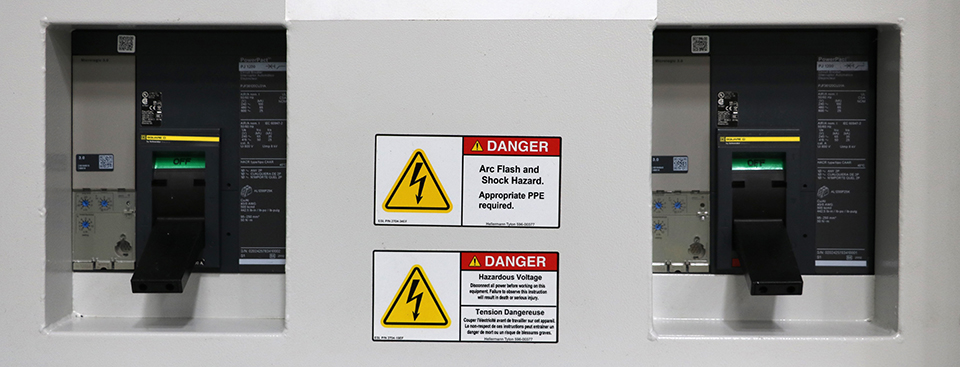
Figure 4: Insulated-case main circuit breakers with key interlock installed in an ESL service entrance docking station.
It is important to specify a mechanical interlock on the docking station; this mechanism prevents the temporary generator installer from gaining access to the terminations before opening the utility circuit breaker. It is also important to consider this point in the electrical system will often see high fault currents since it is so close to the utility transformer. Most manufacturers will be able to provide a 65kA short-circuit interrupting rating as part of their standard offering. If the available fault current exceeds 65kA, a 100kA rated docking station (MTS) must be specified. A 100kA rated docking station (MTS) may not be available from all manufacturers, so it is important to understand what manufacturers can meet this specification requirement should the application call for it.
When implementing a service entrance docking station, the design engineer and installers should pay particular attention to the grounding system connections. The usual methods of installing a main bonding jumper between the grounded service conductor and the equipment grounding bus still apply when installing a docking station. NEC article 250 requires this bonding jumper be installed at either the service transformer or the enclosure of the first disconnecting means, which would be the generator docking station in this case.
Fire pump installation requirements
Fire pump installations have specific requirements outlined in NEC article 695. When applying a generator docking station solution to a project with a fire pump backed up by a generator, special attention should be paid to the location of the fire pump disconnecting means.
A typical design strategy for serving a fire pump from a generator is to provide a dedicated circuit breaker on the generator set. Very often this is an ideal solution for powering a fire pump from the generator, as it allows the conductors to be kept outside of the building all the way from the generator to the fire pump room, therefore eliminating the need to use expensive two-hour fire rated cabling. However, the addition of a generator docking station in an in-line configuration introduces a new problem: the fire pump’s emergency power feeder will not be energized if a temporary generator is utilized while the permanent generator is switched off for maintenance or repair. This situation is the exact opposite of what the introduction of NEC 700.3(F) is trying to achieve. One possible solution to this problem is installing the fire pump disconnecting means directly adjacent to the docking station with the conductors tapped from the load bus of the docking station.
An alternate method for feeding the fire pump from the generator is providing a feeder from a common generator bus such as a distribution panelboard or switchboard. In this setup, the fire pump feeder overcurrent device will be energized when the docking station is powered from a temporary generator. However, depending on the location of the fire pump room, this situation may require the use of two-hour fire rated cabling if the feeder is to be routed within the building. The implications of putting the fire pump disconnecting means at a convenient location such as generator equipment should be evaluated to determine if the advantages outweigh any additional costs.
Engine start considerations
A code requirement that cannot be overlooked is the engine starting requirements for temporary emergency power sources. NEC 700.3(F)(2) references the same code article (NEC 700.12) that applies to permanently installed generators, which requires the generator to start and transfer the load within 10 seconds. To comply with this requirement, engine start wiring should be provided from the transfer switch generator start terminals to the docking station, as this will provide a convenient point for the temporary generator installer to access the start signal wiring.
Accessories for docking stations
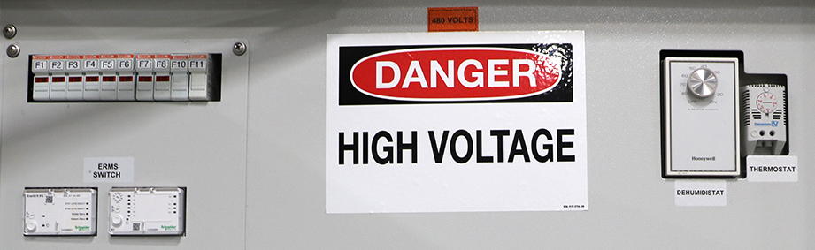
Docking stations have many optional accessories that should be considered for inclusion based on the application requirements. Common available accessories are listed below (Figure 5).
Figure 5: Typical docking station accessories (from left to right): Fuses, ERMS Switches, dehumidistat, and thermostat.
1. 2-wire auto start contacts:A set of posts that provides a convenient and readily accessible set of contacts for connecting the auto start signal from the building transfer switches to the temporary generator.
2. Convenience receptacles/shore power connections:Many temporary generators have separate power connections for jacket water heaters, space heaters, battery chargers and service receptacles. Receptacles can be provided integral to the docking station to keep all the connections in a single convenient location. Most temporary generator optional connections are 120V. These connections are typically only necessary for applications where the temporary generator may be sitting idle for a period of time.
3. Load shed receptacle:For applications where the docking station is serving as a connection point for a load bank, this feature will allow the load bank to automatically be shed if the utility power goes down during a load bank test.
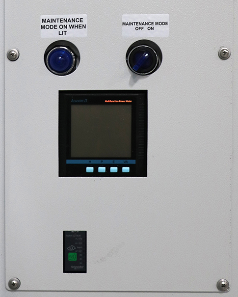
4. Utility indicator lights:Lights which illuminate when the utility voltage is present. This feature can be helpful for the contractors to confirm that utility has been restored before disconnecting the temporary generator (Figure 6).
5. Thermostat and strip heater: Prevents condensation accumulation inside the docking station cabinet.
6. Phase rotation monitor: This device helps the contractor verify the temporary generator phase rotation is correct before energizing the load. It should be noted that NEC 700.3(F) requires this accessory for docking stations serving emergency systems. Even in situations where a phase rotation monitor is not code required, it is recommended that this accessory be provided (Figure 6).
Figure 6: Phase rotation monitor and indicator lights.
How generator docking stations help
Adding a generator docking station can be a very useful solution for complying with current codes and improving system reliability during generator maintenance and repairs. However, the introduction of another system component can increase complexity, so it is critical that docking station installations receive a detailed engineering design to provide a safe and reliable system.
If you’re looking for assistance on specifying or designing a generator docking station, ESL can help! Contact our team now.
Generators and emergency power systems are essential to enabling hospitals and health care facilities to effectively serve their communities
Learning Objectives
Gain a basic understanding of the generators and major components of an emergency power system for hospitals.
Understand the regulatory requirements for an emergency power system for hospitals.
Provide an approach to the design of these systems that accounts for key client and project needs.
Due to constant changes in medical standards of care, technologies and building systems, hospitals have become more reliant on electrical systems to function properly. As such, the reliability of the hospital building’s electrical system is more important than ever.
NFPA 70: National Electrical Code requires every hospital to have two independent power sources that provide a minimum level of reliability: a normal source (i.e., utility) and an alternate source (i.e., generator, fuel cell system or battery system).
Because most health care facilities have traditionally used generators as their alternate source due to runtime and maintenance advantages, this article will focus on generators and essential electrical system (i.e., “emergency power”) design.
For the purposes of this article, the NEC Article 517 term “essential electrical system” and Article 700 term “emergency power system” are synonymous because emergency systems are defined in NEC Article 700, which is applied specifically to hospitals in NEC Article 517.
An emergency system is defined by the NEC as “those systems legally required and classed as emergency by municipal, state, federal and other codes.”
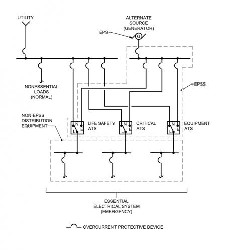
The EPS is the alternate power source, which in this case is the generator(s). The EPSS consists of the conductors, distribution equipment, overcurrent protective devices, transfer switches and all control, supervisory and support equipment needed for the system to operate between the generator and the transfer switch. Conductors, distribution equipment and overcurrent protective devices on the load side of the transfer switches are not considered part of the EPSS per NFPA 110, but are considered part of the overall emergency power system (see Figure 1).
Figure 1
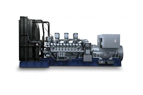
A generator consists of two major components: the engine that provides the mechanical power via a rotating drive shaft and an alternator, which converts the mechanical energy to electrical energy. A transfer switch is an electrical piece of equipment that is configured to connect two incoming power sources (typically the utility source and the generator source) and one outgoing connection to the load(s) using a switching mechanism to select which of the two incoming sources is connected to the load (see Figure 2).
Figure 2: Typical generator set configuration with major components identified (this example is an indoor installation).
There are other regulatory bodies, codes and organizations that need to be considered depending on where the project is located:
NFPA 99: Health Care Facilities Code establishes criteria for levels of health care services to minimize the hazards of fire, explosion and electricity to patients, staffs and visitors.
Reviewing the requirements of these regulatory bodies, codes and publications is recommended at the onset of a new project to determine any project specific impacts as the adopted codes vary by state and local jurisdictions.
Emergency power design considerations
Generators are manufactured with two ratings: prime and standby. A prime rated generator is designed to be operated continuously as the primary source of power for the system, typically used where utility power is not available such as extremely rural locations. A standby rated generator is designed to operate intermittently when the main source of power fails or during generator testing. Emergency power systems for hospitals use generators rated for standby use because the generator is functioning as the alternate source of power.
NFPA 110 requires generators and the EPSS to have a Classification, Type and Level. The “Class” defines the minimum run time in hours. The “Type” defines the maximum time, in seconds, to transfer to the alternate source after power loss. The “Level” defines the risk to human life due to the failure of the system.
Hospital emergency power systems typically must be Class 96 (minimum 96 hours of runtime) or have an operational plan to supply 96 hours of fuel to the site, Type 10 (maximum 10 seconds to transfer) and Level 1 (failure of system could result in loss of human life or serious injuries).
The two common fuel types for hospital generators are No. 2 diesel and natural gas. Typically, hospitals opt to install diesel generators for two primary reasons.
Hospitals are required to either have 96 hours of fuel stored on-site or an agreement to have the additional fuel delivered to maintain 96 hours of continuous runtime (see the Joint Commission’s Emergency Management 96 Hour Plan for details). Natural gas is delivered to the hospital from the utility via underground distribution piping and cannot be stored on-site in the quantities required. Authorities having jurisdiction do not typically consider an off-site fuel source reliable enough to be the sole fuel source for generators (see NEC 700.12(D)(2)).
Emergency generators and the EPSS for hospitals are required to be NFPA 110 Type 10 systems. This requires the system to restore power to the loads in less than 10 seconds. Most natural gas generators are not able to meet this requirement due to the time it takes the generator engine to start.
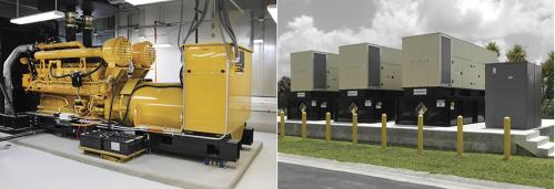
Generators can be installed indoors or outdoors. Indoor installations have the advantage of being better protected from weather and vehicular traffic and provide ease of maintenance but are typically a higher first cost. The generator room needs to be designed to account for the substantial airflow required to both cool the generators and provide combustion air to the generator. Ideally the air intake is at the back of the room and air discharge is at the front to promote proper airflow over the engine block to facilitate engine cooling. Rooms with air intake or discharge from above or one side of the room may create cooling issues and should be avoided. Design also needs to consider the acoustical impact of the generators at both the air intake and discharge locations. Generators create a lot of noise and sound attenuation within the room may be required to meet local ordinances or hospital requirements (see Figure 3).
Figure 3: Example of an indoor (left) and outdoor (right) generator installation
Outdoor installations typically have a lower first cost but are not as accessible and may be susceptible to degradation of the equipment over time if not properly protected. Typically, a generator installed outdoors will have a weather-proof enclosure with dampers and heating elements to keep the environment within the enclosure controlled to an extent. The enclosure also may have a sub-base tank for fuel storage, sound attenuation or raised personnel platforms depending on the specific requirements of the project. The self-contained nature of an outdoor generator can be advantageous as the issues with ventilation and fuel oil delivery are simplified.
Emergency power distribution equipment
The complete essential electrical system, as defined by NEC Article 517, consists of the EPSS (i.e., everything between the transfer switch and the generator, including the transfer switch) and the switchboards, panels, transformers, feeders and overcurrent protective devices that are connected to the load side of the transfer switch.
In hospitals, the essential electrical system is divided into three separate branches per NEC Article 517: life safety, critical and equipment. Each branch has its own automatic transfer switch, or switches depending on the size of the system, to segregate power distribution in the hospital:
The life safety branch is limited to circuits essential to life safety and include illumination of means of egress, exit signs, select alarm and alerting systems, communication systems, generator set accessories, elevators and select automatic doors.
The critical branch is primary reserved for systems and equipment that are essential to patient care and safety and include, but is not limited to, task illumination and receptacles patient care spaces, nurse call systems, clinical information technology systems and select power circuits needed for effective hospital operation.
The equipment branch primarily consists of mechanical equipment required for effective hospital operation and typically includes air handling units, pumps, boilers, chillers, medical vacuum/compressed air equipment, kitchen equipment and any other optional loads the hospital considers necessary to maintain the facility when utility power is lost.
Transfer switches can be either automatic, nonautomatic or manual. Hospitals primarily use automatic transfer switches, which transfers to generator without personnel input. However, nonautomatic and manual transfer switches are used for optional loads when automatic transfer is not required or desired due to available generator capacity.
The difference between nonautomatic and manual is nonautomatic has an automatic transfer mechanism, but transfer requires personnel to initiate; manual requires personnel to physically move a mechanism by hand from one source to the other.
Automatic transfer switches have three transition types. Open transition is the most common in hospitals and disconnects from the primary source of power (utility) before connecting to the alternate source (generator), also known as “break before make.” Delayed transition is similar to open transition but has a built-in time delay where it is disconnected from both sources for an extended period and is most commonly used for mechanical equipment to allow time for motors to slow down before connecting to another source of power.
Closed transition is less common due to utility company approval needed before installation because closed transition briefly parallels utility with the generator(s). Closed transition will briefly connect to both sources before disconnecting from one source or “make before break.” The advantage is the facility does not experience a brief “blip” in power during monthly generator tests or when transferring from generator back to utility power.
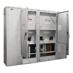
Pictured: 3-Way Manual Transfer Switch includes three breakers which allow the permanent generator to be simultaneously connected to both a load bank (permanent generator testing) and the ATS
Many hospitals require automatic transfer switches to have bypass isolation. Bypass isolation is a switch provided with two switching mechanisms configured so that one switch can be removed and worked on in a safe manner while the other switching mechanism provides power to the loads. The design needs to consider the increased footprint and cost for bypass isolation switches over transfer switches with a single switching mechanism.
Common emergency power system configurations
There are two common system configurations that most hospitals use: standalone and paralleled systems. A standalone system consists of a single generator with transfer switches separating life safety, critical and equipment branch loads. The generator starts when a start signal is received from any of the transfer switches and each transfer switch will transfer to generator power once the switch senses the generator source has reached system voltage and frequency.
The advantage of a standalone system is typically lower first cost in comparison to a similarly sized multi-generator configuration as well as less complicated controls. The disadvantage is failure of the singular generator results in the facility having no backup power to essential loads during the utility outage. In addition, the standalone system has no ability to shed less critical loads if the generator is unable to keep up with the demand load of the facility during the utility outage unless a building automation system interface is provided to monitor real-time load on the generator and shutdown select equipment when it senses the generator is reaching peak capacity. This additional feature will add cost to the project if implemented, which needs to be considered during design.
A paralleled configuration consists of two or more generators connected in parallel to a common bus with multiple transfer switches. Once a start signal is sent by a transfer switch, the first generator to reach rated voltage and frequency will close to the bus. Transfer switches will start transferring to the generator source and subsequent generators will close to the common bus once they reach voltage/frequency and are synchronized with the first generator.
The advantage of paralleled configuration is it provides equipment redundancy in the event a generator fails to start or is offline for repairs. Additionally, the system is able to load shed lower priority transfer switches (i.e., disconnect them from the generator source) if the generators are unable to keep up with the demand load. This prevents a complete outage to the facility and ensures the most critical loads remain operational.
Electrical system redundancy
Hospitals are constantly preparing for the worst-case scenario to ensure they deliver the highest level of care to their patients. Equipment and system redundancy is a priority. It is recommended that designers discuss equipment and system configurations that provide inherent redundancy with the client to ensure the design meets the client’s redundancy requirements and project budget.
For generators, a common configuration is to provide the quantity of generators that provide N+1 redundancy in the event one of the generators fails to start or is offline for repair. For example, if a facility has a peak demand load of 900 kilowatts and the hospital wants N+1 redundancy, providing three 500-kilowatt generators in a paralleled configuration would meet the redundancy goal.
Another strategy to improve the resiliency of the essential electrical system is to separate critical or equipment branches of emergency power into “Critical A” and “Critical B,” each having its own automatic transfer switch. This limits the potential outage to the facility due to a catastrophic failure to a transfer switch or other distribution equipment on that branch of power. It also allows for critical care areas of the hospital to be connected entirely to emergency power while maintaining two separate sources of power which is required by code.
Generator fuel
As previously noted, No. 2 fuel oil is the most common fuel source for hospital emergency generators. Typically, a hospital will have a minimum of 96 hours of fuel on-site, and may have less if complying with the Joint Commission’s Emergency Management 96 Hour Plan or in a local jurisdiction that has a less stringent requirement.
Depending on the utility’s reliability, the generators may only run 15 to 20 hours a year to meet the monthly/yearly testing requirements for each generator. This results in fuel that may sit for extended periods before being used. To avoid degradation of the quality of fuel, most hospitals will install a fuel polishing system to remove water and other particulates from the fuel oil. If a centralized tank is installed to serve multiple generators, a fuel oil pumping system will supply and return fuel to the generator day tanks that are located at each generator.
Modifications, upgrades to existing electrical systems
When designing a generator or emergency power system upgrade for an existing hospital, phasing and outages need to be considered at the outset of the design as they can have a huge impact on hospital operations. Hospitals cannot afford to shut down critical services at any time.
Although outages are unavoidable with a major system upgrade, discussions with hospital administration and key personnel early in the design is crucial as it may require a different design approach to meet the project goals and maintain the facility during construction.
Generators and emergency power systems are an essential system in hospitals to ensure the operational impact of a utility outage is minimal. As health care facilities and staff continue to adapt to the latest standards of care, the need for more robust and reliable emergency power systems will be required.
When initiating the design of a new emergency power system or upgrade to an existing system, owners and design professionals need to be in constant communication to ensure the design aligns with the project goals, budget and hospital’s operational priorities.
Emergency generators and the design of power systems play a crucial role in ensuring reliable power is provided at each facility by providing an alternate source of power in the event the utility source is interrupted.
Announcing DualConnect™, ESL’s New Dual Purpose Docking Station
CORONA, California, October 22, 2021 – ESL Power Systems provides a number of solutions for the growing market to both load bank test, and provide temporary back up to a permanent generator.
For over 10 years, the ESL TripleSwitch® has provided the leading solution to perform both of these functions, and meets the required NEC codes for this application. ESL is now excited to announce the addition of yet another UL 1008 Listed Emergency Power Connection Solution, The DualConnect™ Dual Purpose Docking Station!
Available from 400 to 5,000 amps and rated up to 65kAIC@600VAC, ESL is now the only manufacturer that can provide a complete line of UL 1008 Listed Emergency Power Connection Solutions for all your design needs.
The TripleSwitch is the cost effective, most user-friendly solution for new construction design or adding a permanent generator to an existing facility. Utilizing the (3) circuit breakers necessary for this type of application, it provides the overcurrent protection and safety interlock between permanent and portable generator, without the need for key locks or breakers in separate locations.
The standard TripleSwitch is configured with an AUX Contact for the remote annunciator. It is also provided with -a shunt trip on the load bank breaker, to dump the power to the load bank, in case utility power is lost during a load bank test. This meets the requirements of NEC Code 2017 700.3 (F).
However, there are applications where multiple generators or existing generators need the ability to be load bank tested and also have provision for a connection of a back-up temporary, portable generator. For these projects ESL’s DualConnect – Dual Purpose Docking Station is the right solution for the application.
Where multiple generators are utilized, the design will typically include the necessary switchgear and controls to selectively perform your load bank test or temporary back-up of the permanent generator. In addition, many existing permanent generators need back-up and the capability to do lower cost portable load bank connection.
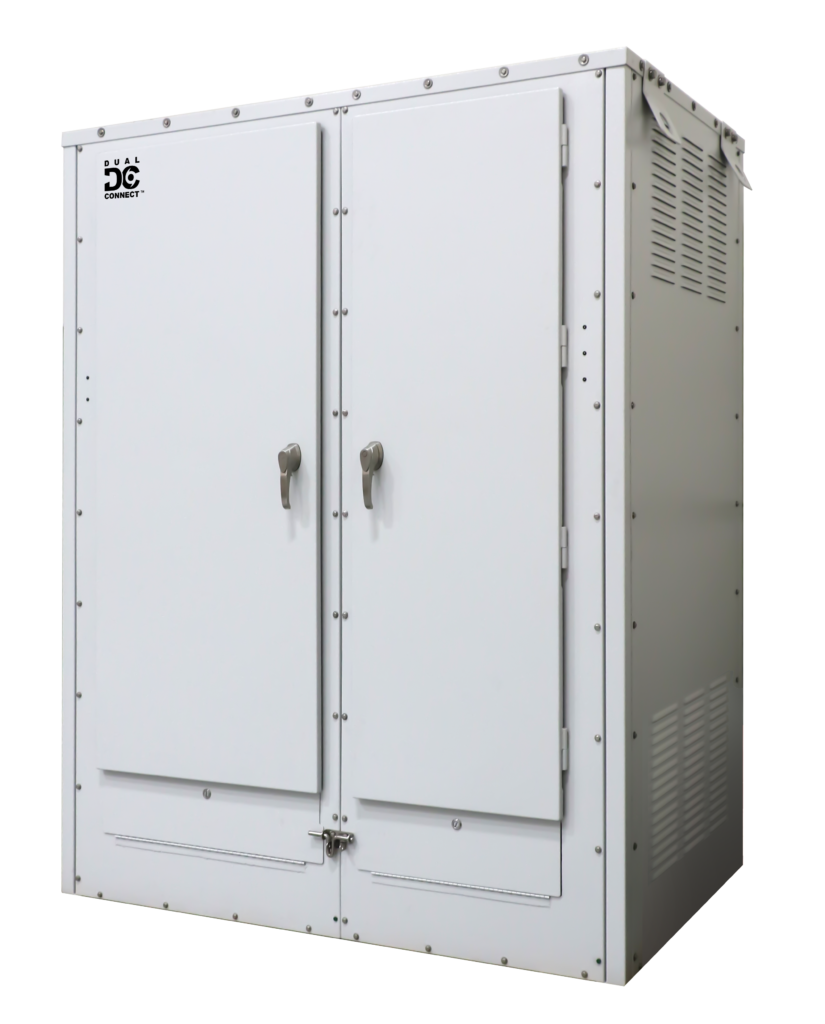
300A DualConnect™
Having a single unit to quickly connect a portable load bank or portable generator while using the existing switchgear overcurrent protection when possible minimizes the total project cost and redundant overcurrent devices.
The Dual Connect – Dual Purpose Docking Station provides the flexibility needed to meet your design criteria and is highly customizable with various optional features. Depending on the emergency back-up system design for multiple or existing generators, the DualConnect is available in three different versions.
No Breaker: Where all the controls and/or breakers are currently in the emergency power system. The interlock between the permanent generator and temporary back-up generator is accomplished by a key interlock between an appropriate designated breaker and the DualConnect portable generator cable access door.
One Breaker: Provides overcurrent protection to the unit and functions as the disconnect for both the load bank and portable generator cams. The interlock between the permanent generator and temporary back-up generator is accomplished by a key interlock between an appropriate designated breaker and the DualConnect portable generator cable access door.
Two Breakers: Provides overcurrent protection to the unit and functions as the disconnects for both the load bank and portable generator cams. The interlock between the permanent generator and temporary back-up generator is accomplished by a key interlock between an appropriate designated breaker and the portable generator breaker in the DualConnect. All of ESL’s DualConnect units with 2 breakers can be configured to meet NEC700.3(F) if required.
A 100% employee owned company, ESL Power Systems, Inc. is an innovative global leader in the design and manufacturing of cord-connected electrical equipment for industrial and commercial applications and is also the premier custom control panel builder in Southern California.
Media Contact: Erika Thorson ESL Power Systems, Inc. 2800 Palisades Dr. Corona, CA 92878 +1 (951) 739-7000 ethorson@eslpwr.com https://eslpwr.com
Natural events have become a common occurrence in many parts of the US with a growing number of devastating natural disasters occurring in recent years. Preparing your business for emergency back-up power in the midst of a natural disaster such as an earthquake, hurricane, ice storm or flood is crucial for business continuity.
Earthquakes
In the US alone, the National Earthquake Information Center locates about 12,000-14,000 earthquakes per year. Globally there are approximately 55 earthquakes per day averaging out to 20,000 a year!
During an earthquake, a building’s emergency equipment may inevitably experience vigorous shaking and movement depending on the magnitude. Acquiring back-up equipment that is OSHPD “OSP” Special Seismic Certified provides enormous value in knowing your equipment has been shaker-table tested and certified to endure major earthquakes without fail. However, earthquakes aren’t just about shaky buildings, earthquakes also have the power to cause damage to electrical grids and powerlines. When either of the two are down, electricity and power can go out resulting in a loss of power to your business. This ultimately results in loss revenues, product and production to name a few. Where critical facilities are concerned, this could mean life or death.
Wind and Storms
High winds from hurricanes, tornadoes, and severe storms affect emergency power every year and are one of the most common causes of power outages. In 2020, NOAA reported a record-breaking 30 named storms (top winds of 39 mph or greater), of which 13 became hurricanes (top winds of 74 mph or greater), including six major hurricanes (top winds of 111 mph or greater). 2020 became the year with the most storms ever recorded in the continental United States. A report from Climate Central states that 44 percent of power outages are caused by storm events which negatively impact businesses and homes.
Strong winds tend to blow large debris resulting in broken power lines and utility poles. They can also cause lines to swing together which can result in short circuiting utility power. Strong winds are also traced to the cause of wildfires. Utility companies have begun to implement “Public Safety Power Shutoffs” in order to tackle the event of severe winds and prevent wildfires from occurring. With consistent power outages during severe winds, businesses are forced to find alternatives to utility power in order to keep the lights on during these long shutoffs.
Ice Storms
Ice storms fall into the “winter weather” category and occur in the U.S. primarily during the months of December and January. Also known as freezing rain, these storms occur when rain freezes and accumulates on surfaces such as trees, power lines, and the ground.
Severe damage to trees and power lines begins when ice accumulates between a quarter- and half-inch. When these ice droplets accumulate onto powerlines it can add up to 500 pounds of extra weight. With the amount of weight added by ice layers, trees and utility lines tend to fall and result in damage to roads, homes, and businesses. It can take quite a while for trees to be removed from roads and powerlines to be repaired, this can result in a loss of electricity and heat for many days. In January 2020, an Atlanta ice storm left half a million people without power, some for more than a week while utility companies tried to repair lines. Estimated total losses reported for this storm reached upwards of $48 million. In mid-December of 2020, an ice storm left more than 500,000 without power in parts of Texas, Oklahoma and Arkansas. At the time, it was called one of the most destructive ice storms seen to the electrical utility infrastructure in those areas. In February 2021 more than 700,000 people were without power due to ice storms in eight states including Nevada, Oregon, Washington, Kentucky, North Carolina, West Virginia, and Virginia.
Knowing that ice storms can last up to a few days, preparing ahead of time is the best decision. Businesses with back-up power solutions are able to sustain these winter events and keep the lights and heat on when it is needed the most.
Floods
According to the department of agriculture, ninety percent of all natural disasters in the United States involve flooding. Additionally, high-risk flood areas are not the only ones at risk, about 25% of flood insurance claims come from moderate-to low-risk areas.
Floods are caused by spring thaw resulting in the overflow of rivers, waterways, dams, etc. They are also caused by coastal flooding due to hurricanes, tropical storms, and heavy rains. Flood surges that occurred in Hurricanes such as Sandy and Katrina severely affected emergency power. Flood damage poses one of the greatest risks to on-site power.
Considering the location of your emergency back-up equipment is paramount when planning for possible flood-damage. The lowest level of a building is the most likely to flood knocking out emergency power distribution equipment, such as transfer switches, rendering switches inoperable. Organizations such as Medical facilities and Universities have begun mounting back-up equipment on the second floor keeping all equipment dry and operational during a flood.
Natural disasters are in abundance. All the U.S. incurs some sort of natural disaster that knocks out power daily. Designing on-site emergency power back-up systems is crucial to business survival and recovery.