Corona, CA and Lund, Sweden — May 2024 — ESL and Elonroad are pleased to announce their partnership aimed at developing innovative automatic charging solutions for essential businesses and supply chains. The collaboration will focus on leveraging Elonroad’s automatic charging technology and ESL’s expertise in power system solutions to electrify the future of transportation sustainably.
The partnership signifies a strategic move by both companies to address the growing need for efficient and climate-friendly charging solutions, particularly within the Electric Transport Refrigeration Unit (ETRU) market, including refrigerated trucks, trailers, and warehouses. This collaboration also marks Elonroad’s introduction to the U.S. market, introducing the availability of cutting-edge automatic charging solutions.
The joint venture will kickstart with a pilot program, set to commence in mid-2024 and conclude by Q1 2025. This U.S. market initiative aligns with the shared vision of both parties to revolutionize the transportation sector and reduce dependence on fossil fuels.
Carlos Valero, Chief Operating Officer of ESL, highlighted the synergies between the two companies, stating, ” Elonroad’s unique automatic charging solutions significantly decrease CO2 impact and lowers the total cost of ownership, offering the flexibility to charge electric vehicles whether on the move or parked. This innovation aligns with ESL’s commitment to providing sustainable solutions that drive environmental benefits while meeting the evolving needs of the transportation industry. Together, we aim to redefine the future of our markets.”
Karin Ebbinghaus, CEO of Elonroad, expressed her thoughts on the partnership, saying, “We recognize ESL as an industry leader, and partnering with them in the U.S. market is a key strategic move for Elonroad. Through this collaboration, we are thrilled to forge a path toward a positive future where sustainable practices and safety for all involved are paramount. This partnership not only underscores our commitment to climate-consciousness but also signifies a significant step towards redefining industry standards. We look forward to the innovative solutions and positive impact our combined efforts will bring to the transportation sector and beyond.”
Elonroad specializes in charging solutions for electric vehicles, catering to various segments such as commercial, private, light, and heavy vehicles, both autonomous and human-operated. Working with, amongst others, one of the leaders within circular services, in addition also building the first electric highway together with VINCI outside Paris, France. Meanwhile, ESL is renowned for its advanced power system solutions in the electric vehicle charging industry and renewable energy applications.
The partnership between ESL and Elonroad marks a significant step towards sustainable transportation and underscores their commitment to innovation and environmental stewardship.
About ESL
ESL is a leader in developing, manufacturing, and integrating advanced power system solutions for the electric vehicle (EV) charging industry and renewable energy applications. With a robust portfolio that includes everything from high-efficiency charging stations to innovative power management systems, ESL is at the forefront of supporting sustainable transportation.
About Elonroad
Elonroad, a Swedish cleantech company, aims to streamline energy flow using their innovative technology for Electric Roads (ERS) and automated charging stations, targeting industries like logistics and ports. Their technology, which integrates conductive charging into road surfaces, enables vehicles to charge while moving or parked. Enhanced with IoT sensors, the system optimizes charging, improves safety, and operates efficiently 24/7 while also reducing CO2 emissions. Elonroad collaborates with major partners like logistics company Elis and global supplier of automotive components Aisin and is currently working on the first electric highway on the A10 highway outside Paris, France. Elonroad’s charging solutions support all types of electric vehicles—commercial or private, light or heavy, autonomous or manual—further expanding their reach and impact in the shift towards sustainable transportation.
The National Fire Protection Association (NFPA) 70B standard sets forth standards for “Electrical Equipment Maintenance”. In its 2023 edition, chapter 9 of NFPA 70B transitions from a “Recommended Practice” to a more structured “Standard” with a heightened emphasis on mandatory compliance. However, unlike the National Electric Code (NEC), which is adopted by states as law, NFPA 70B is not directly mandated by law and should be regarded as a foundational guideline for ensuring electrical safety.
NFPA 70B aims to establish an Electrical Maintenance Program geared towards enhancing safety and reliability. The 2023 edition of NFPA 70B introduces new classifications for physical conditions of equipment (referred to as Levels 1, 2, and 3), which dictate the frequency of maintenance, ranging from 6 to 60 month intervals, contingent upon the product category.
When conducting maintenance, it is always advisable to adhere closely to the recommendations and instructions provided by equipment manufacturers, as this represents a best practice approach to ensure optimal performance and safety.
How does ESL’s equipment help comply with NFPA 70B?
When using portable generators in conjunction with an ESL StormSwitch®, TripleSwitch®, DualConnect™, or RotaryConnect™ system, it’s essential to ensure seamless operation. To do so, first disconnect the portable generator from the ESL unit. Then, connect a portable load bank to the portable generator in accordance with the generator manufacturer’s recommended maintenance instructions. This ensures efficient and reliable performance of the generator. For permanent generators integrated with an ESL TripleSwitch® or DualConnect™ system, a similar approach applies. In this case, simply connect a portable load bank to the output CAMs on the ESL unit, adhering closely to the generator manufacturer’s maintenance guidelines. This step facilitates optimal functioning and longevity of the generator setup within the ESL system.
To contact ESL for additional questions or a quote, click here.
Generators and emergency power systems are essential to enabling hospitals and health care facilities to effectively serve their communities
Learning Objectives
Gain a basic understanding of the generators and major components of an emergency power system for hospitals.
Understand the regulatory requirements for an emergency power system for hospitals.
Provide an approach to the design of these systems that accounts for key client and project needs.
Due to constant changes in medical standards of care, technologies and building systems, hospitals have become more reliant on electrical systems to function properly. As such, the reliability of the hospital building’s electrical system is more important than ever.
NFPA 70: National Electrical Code requires every hospital to have two independent power sources that provide a minimum level of reliability: a normal source (i.e., utility) and an alternate source (i.e., generator, fuel cell system or battery system).
Because most health care facilities have traditionally used generators as their alternate source due to runtime and maintenance advantages, this article will focus on generators and essential electrical system (i.e., “emergency power”) design.
For the purposes of this article, the NEC Article 517 term “essential electrical system” and Article 700 term “emergency power system” are synonymous because emergency systems are defined in NEC Article 700, which is applied specifically to hospitals in NEC Article 517.
An emergency system is defined by the NEC as “those systems legally required and classed as emergency by municipal, state, federal and other codes.”
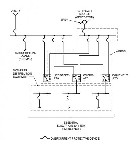
The EPS is the alternate power source, which in this case is the generator(s). The EPSS consists of the conductors, distribution equipment, overcurrent protective devices, transfer switches and all control, supervisory and support equipment needed for the system to operate between the generator and the transfer switch. Conductors, distribution equipment and overcurrent protective devices on the load side of the transfer switches are not considered part of the EPSS per NFPA 110, but are considered part of the overall emergency power system (see Figure 1).
Figure 1
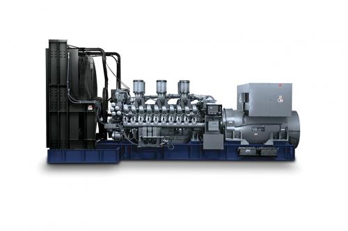
A generator consists of two major components: the engine that provides the mechanical power via a rotating drive shaft and an alternator, which converts the mechanical energy to electrical energy. A transfer switch is an electrical piece of equipment that is configured to connect two incoming power sources (typically the utility source and the generator source) and one outgoing connection to the load(s) using a switching mechanism to select which of the two incoming sources is connected to the load (see Figure 2).
Figure 2: Typical generator set configuration with major components identified (this example is an indoor installation).
There are other regulatory bodies, codes and organizations that need to be considered depending on where the project is located:
NFPA 99: Health Care Facilities Code establishes criteria for levels of health care services to minimize the hazards of fire, explosion and electricity to patients, staffs and visitors.
Reviewing the requirements of these regulatory bodies, codes and publications is recommended at the onset of a new project to determine any project specific impacts as the adopted codes vary by state and local jurisdictions.
Emergency power design considerations
Generators are manufactured with two ratings: prime and standby. A prime rated generator is designed to be operated continuously as the primary source of power for the system, typically used where utility power is not available such as extremely rural locations. A standby rated generator is designed to operate intermittently when the main source of power fails or during generator testing. Emergency power systems for hospitals use generators rated for standby use because the generator is functioning as the alternate source of power.
NFPA 110 requires generators and the EPSS to have a Classification, Type and Level. The “Class” defines the minimum run time in hours. The “Type” defines the maximum time, in seconds, to transfer to the alternate source after power loss. The “Level” defines the risk to human life due to the failure of the system.
Hospital emergency power systems typically must be Class 96 (minimum 96 hours of runtime) or have an operational plan to supply 96 hours of fuel to the site, Type 10 (maximum 10 seconds to transfer) and Level 1 (failure of system could result in loss of human life or serious injuries).
The two common fuel types for hospital generators are No. 2 diesel and natural gas. Typically, hospitals opt to install diesel generators for two primary reasons.
Hospitals are required to either have 96 hours of fuel stored on-site or an agreement to have the additional fuel delivered to maintain 96 hours of continuous runtime (see the Joint Commission’s Emergency Management 96 Hour Plan for details). Natural gas is delivered to the hospital from the utility via underground distribution piping and cannot be stored on-site in the quantities required. Authorities having jurisdiction do not typically consider an off-site fuel source reliable enough to be the sole fuel source for generators (see NEC 700.12(D)(2)).
Emergency generators and the EPSS for hospitals are required to be NFPA 110 Type 10 systems. This requires the system to restore power to the loads in less than 10 seconds. Most natural gas generators are not able to meet this requirement due to the time it takes the generator engine to start.
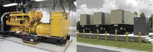
Generators can be installed indoors or outdoors. Indoor installations have the advantage of being better protected from weather and vehicular traffic and provide ease of maintenance but are typically a higher first cost. The generator room needs to be designed to account for the substantial airflow required to both cool the generators and provide combustion air to the generator. Ideally the air intake is at the back of the room and air discharge is at the front to promote proper airflow over the engine block to facilitate engine cooling. Rooms with air intake or discharge from above or one side of the room may create cooling issues and should be avoided. Design also needs to consider the acoustical impact of the generators at both the air intake and discharge locations. Generators create a lot of noise and sound attenuation within the room may be required to meet local ordinances or hospital requirements (see Figure 3).
Figure 3: Example of an indoor (left) and outdoor (right) generator installation
Outdoor installations typically have a lower first cost but are not as accessible and may be susceptible to degradation of the equipment over time if not properly protected. Typically, a generator installed outdoors will have a weather-proof enclosure with dampers and heating elements to keep the environment within the enclosure controlled to an extent. The enclosure also may have a sub-base tank for fuel storage, sound attenuation or raised personnel platforms depending on the specific requirements of the project. The self-contained nature of an outdoor generator can be advantageous as the issues with ventilation and fuel oil delivery are simplified.
Emergency power distribution equipment
The complete essential electrical system, as defined by NEC Article 517, consists of the EPSS (i.e., everything between the transfer switch and the generator, including the transfer switch) and the switchboards, panels, transformers, feeders and overcurrent protective devices that are connected to the load side of the transfer switch.
In hospitals, the essential electrical system is divided into three separate branches per NEC Article 517: life safety, critical and equipment. Each branch has its own automatic transfer switch, or switches depending on the size of the system, to segregate power distribution in the hospital:
The life safety branch is limited to circuits essential to life safety and include illumination of means of egress, exit signs, select alarm and alerting systems, communication systems, generator set accessories, elevators and select automatic doors.
The critical branch is primary reserved for systems and equipment that are essential to patient care and safety and include, but is not limited to, task illumination and receptacles patient care spaces, nurse call systems, clinical information technology systems and select power circuits needed for effective hospital operation.
The equipment branch primarily consists of mechanical equipment required for effective hospital operation and typically includes air handling units, pumps, boilers, chillers, medical vacuum/compressed air equipment, kitchen equipment and any other optional loads the hospital considers necessary to maintain the facility when utility power is lost.
Transfer switches can be either automatic, nonautomatic or manual. Hospitals primarily use automatic transfer switches, which transfers to generator without personnel input. However, nonautomatic and manual transfer switches are used for optional loads when automatic transfer is not required or desired due to available generator capacity.
The difference between nonautomatic and manual is nonautomatic has an automatic transfer mechanism, but transfer requires personnel to initiate; manual requires personnel to physically move a mechanism by hand from one source to the other.
Automatic transfer switches have three transition types. Open transition is the most common in hospitals and disconnects from the primary source of power (utility) before connecting to the alternate source (generator), also known as “break before make.” Delayed transition is similar to open transition but has a built-in time delay where it is disconnected from both sources for an extended period and is most commonly used for mechanical equipment to allow time for motors to slow down before connecting to another source of power.
Closed transition is less common due to utility company approval needed before installation because closed transition briefly parallels utility with the generator(s). Closed transition will briefly connect to both sources before disconnecting from one source or “make before break.” The advantage is the facility does not experience a brief “blip” in power during monthly generator tests or when transferring from generator back to utility power.
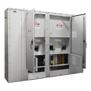
Pictured: 3-Way Manual Transfer Switch includes three breakers which allow the permanent generator to be simultaneously connected to both a load bank (permanent generator testing) and the ATS
Many hospitals require automatic transfer switches to have bypass isolation. Bypass isolation is a switch provided with two switching mechanisms configured so that one switch can be removed and worked on in a safe manner while the other switching mechanism provides power to the loads. The design needs to consider the increased footprint and cost for bypass isolation switches over transfer switches with a single switching mechanism.
Common emergency power system configurations
There are two common system configurations that most hospitals use: standalone and paralleled systems. A standalone system consists of a single generator with transfer switches separating life safety, critical and equipment branch loads. The generator starts when a start signal is received from any of the transfer switches and each transfer switch will transfer to generator power once the switch senses the generator source has reached system voltage and frequency.
The advantage of a standalone system is typically lower first cost in comparison to a similarly sized multi-generator configuration as well as less complicated controls. The disadvantage is failure of the singular generator results in the facility having no backup power to essential loads during the utility outage. In addition, the standalone system has no ability to shed less critical loads if the generator is unable to keep up with the demand load of the facility during the utility outage unless a building automation system interface is provided to monitor real-time load on the generator and shutdown select equipment when it senses the generator is reaching peak capacity. This additional feature will add cost to the project if implemented, which needs to be considered during design.
A paralleled configuration consists of two or more generators connected in parallel to a common bus with multiple transfer switches. Once a start signal is sent by a transfer switch, the first generator to reach rated voltage and frequency will close to the bus. Transfer switches will start transferring to the generator source and subsequent generators will close to the common bus once they reach voltage/frequency and are synchronized with the first generator.
The advantage of paralleled configuration is it provides equipment redundancy in the event a generator fails to start or is offline for repairs. Additionally, the system is able to load shed lower priority transfer switches (i.e., disconnect them from the generator source) if the generators are unable to keep up with the demand load. This prevents a complete outage to the facility and ensures the most critical loads remain operational.
Electrical system redundancy
Hospitals are constantly preparing for the worst-case scenario to ensure they deliver the highest level of care to their patients. Equipment and system redundancy is a priority. It is recommended that designers discuss equipment and system configurations that provide inherent redundancy with the client to ensure the design meets the client’s redundancy requirements and project budget.
For generators, a common configuration is to provide the quantity of generators that provide N+1 redundancy in the event one of the generators fails to start or is offline for repair. For example, if a facility has a peak demand load of 900 kilowatts and the hospital wants N+1 redundancy, providing three 500-kilowatt generators in a paralleled configuration would meet the redundancy goal.
Another strategy to improve the resiliency of the essential electrical system is to separate critical or equipment branches of emergency power into “Critical A” and “Critical B,” each having its own automatic transfer switch. This limits the potential outage to the facility due to a catastrophic failure to a transfer switch or other distribution equipment on that branch of power. It also allows for critical care areas of the hospital to be connected entirely to emergency power while maintaining two separate sources of power which is required by code.
Generator fuel
As previously noted, No. 2 fuel oil is the most common fuel source for hospital emergency generators. Typically, a hospital will have a minimum of 96 hours of fuel on-site, and may have less if complying with the Joint Commission’s Emergency Management 96 Hour Plan or in a local jurisdiction that has a less stringent requirement.
Depending on the utility’s reliability, the generators may only run 15 to 20 hours a year to meet the monthly/yearly testing requirements for each generator. This results in fuel that may sit for extended periods before being used. To avoid degradation of the quality of fuel, most hospitals will install a fuel polishing system to remove water and other particulates from the fuel oil. If a centralized tank is installed to serve multiple generators, a fuel oil pumping system will supply and return fuel to the generator day tanks that are located at each generator.
Modifications, upgrades to existing electrical systems
When designing a generator or emergency power system upgrade for an existing hospital, phasing and outages need to be considered at the outset of the design as they can have a huge impact on hospital operations. Hospitals cannot afford to shut down critical services at any time.
Although outages are unavoidable with a major system upgrade, discussions with hospital administration and key personnel early in the design is crucial as it may require a different design approach to meet the project goals and maintain the facility during construction.
Generators and emergency power systems are an essential system in hospitals to ensure the operational impact of a utility outage is minimal. As health care facilities and staff continue to adapt to the latest standards of care, the need for more robust and reliable emergency power systems will be required.
When initiating the design of a new emergency power system or upgrade to an existing system, owners and design professionals need to be in constant communication to ensure the design aligns with the project goals, budget and hospital’s operational priorities.
Emergency generators and the design of power systems play a crucial role in ensuring reliable power is provided at each facility by providing an alternate source of power in the event the utility source is interrupted.
CORONA, California, October 29, 2020 – ESL Power Systems, Inc., a global leader in providing safety-interlocked power solutions for cord-connected electrical equipment is proud to announce the launch of its newly redesigned website at eslpwr.com. The new ESL website includes redesigned architecture focused on customer ease of use while navigating ESL’s extensive range of product offerings.
Created with the user experience in mind, ESL’s new website includes many updated features to help users quickly and easily navigate the site.
Showcase navigation allows users to easily navigate to any product offering from any page resulting in decreased clicks for site browsing.
Enhanced site search with quick view. Easily search across the entire site for catalog sheets, product specifications or blog posts by entering key words. Hover over search results to see thumbnails of each page.
Ask a Question and Quote Requests buttonsreadily available. ESL’s knowledgeable customer service team is here to help you determine what solution is best for your project. In addition to our online request forms, you can give us a call by tapping our number at the top of any page from your handheld device. Our goal is to easily connect you to one of our exceptional customer service members for project direction in the medium that’s best suited to you.
Determine where to buy our products across the U.S. Visit our new Local Rep Map and find a manufacturer representative group near you.
ESL has also made our helpful videos more accessible including highlights on recently published videos directly on the navigation menu.
“The ESL website is the foundation of our online presence. As our organization focuses on strategic growth, our site functions as a critical tool to establish brand recognition all while making our customers experience a better one,” stated ESL President Marcelo Gonzalez.
ESL is proud of the new website which complements our brand, vision and showcases our company in a way that is reflective of the quality of service and product supplied to our customers. Check it out now!
Media Contact: Erika Thorson ESL Power Systems, Inc. 2800 Palisades Dr. Corona, CA 92878 +1 (951) 739-7000 ethorson@eslpwr.com https://eslpwr.com
CORONA, California, September 24, 2020 – ESL Power Systems, Inc is pleased to announce the appointment of Marcelo Gonzalez as President. Michael Hellmers, who has been President of ESL for nearly 20 years, will continue to be engaged in the business and advance into the position of Chief Sales Strategist and Chairman of the Board.
Recently transitioned to a 100% employee-owned company through its Employee Stock Ownership Plan (ESOP), ESL is primed to tackle exciting challenges and opportunities as we emerge from Covid-19. Marcelo’s appointment is a clear reflection of ESL’s strategic vision as he is enthusiastic to accelerate ESL’s growth.
Marcelo Gonzalez
Marcelo’s key professional attributes include leading international organizations to double-digit growth, developing teams through coaching, and setting clear strategies while aligning teams to achieve a bold vision.
Marcelo holds a Mechanical Engineering degree as well as an MBA. Originally from Argentina, he has lived in several countries while holding key executive positions at Cavotec, based in Switzerland, where he worked for almost 18 years. His last professional challenge was leading the international operations at DART Aerospace.
Marcelo will continue to build the organizational success of ESL, working hand in hand with Michael and David Helmers during the transition.
“I am very excited to be joining ESL,” Marcelo said, “I believe this is a tremendous opportunity to contribute in the continued growth of an organization that already has a great business model and a talented management team. We are well-positioned to bring ESL to a new level of performance and excellence.”
“Marcelo is the right new leader to drive ESL to the next level,” said Michael Hellmers. “There is enormous opportunity ahead, and we couldn’t be happier with Marcelo joining our team to lead ESL and our customers to mutual success.”
About ESL Power Systems, Inc.
A 100% employee owned company, ESL Power Systems, Inc. is an innovative global leader in the design and manufacturing of cord-connected electrical equipment for industrial and commercial applications and is also the premier custom control panel builder in Southern California.

 CORONA, California, September 24, 2020 – ESL Power Systems, Inc is pleased to announce the appointment of Marcelo Gonzalez as President. Michael Hellmers, who has been President of ESL for nearly 20 years, will continue to be engaged in the business and advance into the position of Chief Sales Strategist and Chairman of the Board.