Learning Objectives
- Understand the basic requirements of NEC 240.87.
- Know the importance of arc energy reduction methods and arcing current.
- Learn how different arc energy reduction methods are calculated.
Arc energy insights
- Low-voltage electrical systems and technology require electrical engineers to consider arc energy reduction.
- Zone-selective interlocking systems detect high-level fault conditions, allowing instantaneous tripping in certain situations.
- NFPA 70: National Electrical Code Article 240.87 is vital to electrical engineers working on these systems, as it discusses arc energy reduction.
Since its inclusion in the 2014 edition of the NFPA 70: National Electrical Code, known as NEC, multiple articles have been written in various publications discussing Article 240.87
While the 2014, 2020 and, to a lesser extent, the 2017 versions of the NEC are discussed in this article, any references to the NEC that do not indicate a specific year or edition refer to the 2023 version only. Essential to understanding how to meet the requirements of 240.87 is IEEE 1584: Guide for Performing Arc-Flash Hazard Calculations. Unless otherwise noted, any references to IEEE 1584 in this article refer to the latest version, 2018, and its subsequent addenda. NFPA 70E: Standard for Electrical Safety in the Workplace provides requirements for safe work practices, including those required by NEC 240.87. Additionally, 240.67 arc energy reduction for fuses will only be tangentially mentioned in this article.
Important edits and additions to the NEC’s arc energy reduction requirements include the following:
NEC 2017
- Added 240.67, which requires arc energy reduction when fuses are 1,200 A or greater (240.87 is part of a section specific to circuit breakers).
- Added instantaneous pickup and instantaneous override as options for arc energy reduction.
NEC 2020
- Added clarification regarding arcing fault currents.
- Added clarification that temporary instantaneous pickup adjustments are not satisfactory.
- NEC 2023 included no major changes to 240.87.
240.87 states, “Where the highest continuous current trip setting for which the actual overcurrent device installed in a circuit breaker is rated or can be adjusted is 1,200 amperes or higher,” the three sub paragraphs shall apply. These three subparagraphs are (A) documentation, (B) method to reduce clearing time and (C) performance testing.
240.87(A) Documentation has, since its inception, been straightforward in requiring that information about the system be recorded and available to personnel authorized to work on the equipment. The 2020 version of the NEC added a sentence further detailing these requirements, requiring proof that whatever method is used for arc energy reduction works and is in use.
240.87(A) and 240.87(B) note that the arc energy reduction method “be set to operate at less than the available arcing current,” i.e., that the arc energy reduction system will actually operate based upon the specific system’s characteristics. The writer of this piece assumes these requirements were added to prevent the situation where an unscrupulous system operator would circumvent the intent of 240.87 (protecting personnel) by merely installing an arc energy reduction system but not actually having it operational.
It is important to note that the available arcing current is different from the more commonly encountered available short-circuit current. The available short-circuit current, often called the bolted-fault current, can be found at a given bus by reducing the electrical system to its Thevenin equivalent with zero fault impedance. The available arcing current is similar, with the addition of the impedance of a prospective arc included. At face value, this seems a simple calculation, but in practice, IEEE 1584 uses a selection of five different equations based on parameters such as the electrode configuration, nominal system voltage and electrode gap to determine. Arc flash analysis software can be used to accurately determine the arcing fault current.
It is also vital for personnel to understand that arc energy reduction at one overcurrent-protective device or bus is dependent not on that overcurrent protective device, but on the next overcurrent-protective device(s) upstream or on the line-side of that device. For feeder circuit breakers installed on a switchgear, this could be the main circuit breaker; for that same main circuit breaker, protection would need to be provided by the feeder circuit breaker or relay feeding the main. Exceptions to this may include certain types of energy-reducing active arc flash mitigation systems that reduce the fault energy without the assistance of overcurrent protective devices tripping.
240.87(B) provides a list of acceptable means to reduce arc energies, including: zone-selective interlocking, differential relaying, energy-reducing maintenance switching with local status indicator, energy-reducing active arc flash mitigation system, a permanent instantaneous trip setting, an instantaneous override or an approved equivalent means. Each of these methods, including their advantages and disadvantages, is discussed in the following paragraphs. Note that, as stated earlier, all the methods must be set to operate below the available arcing current.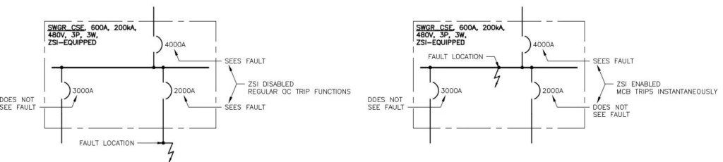
Zone-selective interlocking
ZSI is, at its most simple, a communication system. Overcurrent protective devices are connected such that they communicate with each other when they pick up or “see” a high-level fault condition, allowing instantaneous tripping in certain situations. If both a feeder overcurrent protective device and an upstream main overcurrent protective device pickup on a fault current, the system will operate as usual (i.e., if properly coordinated, the feeder breaker will first attempt to trip the fault). If that same main overcurrent protective device picks up a fault current but none of its associated feeder overcurrent protective device do, the main overcurrent protective device will trip with no intentional delay, regardless of its short-time or instantaneous pickup settings/delays. ZSI systems are generally most common in switchgear systems and can be moderately expensive, especially when interlocking feeder circuit breakers from one switchgear with overcurrent protective devices of a separate switchgear. ZSI is often installed in new switchgear installations. Figure 1 presents a basic visual of a ZSI system for (a) a fault within the ZSI-protected zone and (b) a fault outside the ZSI-protected zone.
Advantages: Fast-acting, allows intelligent zone isolation and selective coordination.
Disadvantages: Moderately expensive, requires interlocking wiring and more advanced circuit breakers, may not be an option between different busses and may not work across multiple manufacturers.
Differential relaying
Differential Relay (ANSI device No. 87) has been used for decades to efficiently detect and isolate faults within a zone of protection, whether that be a bus, cable, transformer or other equipment. As the name implies, if the difference in value between the currents entering and exiting a node is not zero or within a prescribed setting, the relay will trip all such devices. Differential relaying, due to its cost, is usually restricted to large or critical switchgear, transformer, motor or generator systems.
Advantages: Extremely fast-acting, does not impact selective coordination. Modern relay systems provide some security against nuisance tripping.
Disadvantages: Expensive — each circuit requires current transformers and associated wiring; current transformers must be properly matched and/or of sufficient quality and size to prevent through-fault nuisance tripping.
Energy-reducing maintenance switching with local status indicator
Maintenance switching with local status indication generally involves a physical switch and light installed on a piece of equipment. If personnel are going to work on said equipment energized, they would toggle the switch, which would send a signal to the next upstream overcurrent protective device to lower its instantaneous settings to minimum. This allows for a system to maintain coordination under normal operating conditions while also limiting arc hazards to personnel during maintenance or other activities.
It is important to reiterate that to be effective, the maintenance switch must lower the instantaneous setting of the upstream overcurrent protective device, not of the device in the cubicle or equipment associated with the work. Maintenance switching is often found in new switchgear installations, though can be retrofitted into existing systems. Figure 2 presents a basic time-current curve for a circuit breaker system with maintenance switching (a) inactive and (b) active.
Advantages: Relatively cheap compared to the other arc reduction options, excepting instantaneous trip/override; may be installed in new or existing systems; provides both selective coordination and personnel protection.
Disadvantages: Relies on administrative controls to ensure personnel use the system properly for protection — if the system is not engaged when working on equipment, the personnel may not be protected. If the system is not disengaged after work is complete, the system may experience nuisance tripping. In theory, the local status indicator should limit such occurrences, but anecdotally, the latter can be common.
Arc energy-reducing active arc flash mitigation system
Multiple types of energy-reducing active arc flash mitigation systems exist. One of the most common is an arc flash relay system, which normally uses both light sensors and overcurrent pickup to detect an arc flash event and isolate the equipment. Such systems have been around for over a decade and can generally be installed in both new and existing equipment.
Another type of active arc flash mitigation system is the ultrafast earthing switch, which introduces a controlled three-phase line-to-ground fault when sensing arc fault conditions; this fault (of essentially zero impedance) effectively redirects the fault current to an area where it can be contained in a safe manner. UFES systems have advanced greatly in recent years, going from large contraptions that are little more than electrodes fired from shotgun shells into the ground to units that can be installed as parts integral to a switchgear setup.
Arc-quenching is a third type of active arc flash mitigation system that is similar to the arc flash relay system in structure — light sensors and current transformers — and the UFES system in response time. Whereas UFES systems introduce a controlled three-phase bolted fault, arc-quenching systems introduce current-limiting devices to control and redirect the fault current.
Advantages: Regardless the technology, active arc flash mitigation systems provide extremely quick response times to detect and/or isolate an arc. Additionally, while passive arc energy reduction systems — specifically arc-rated equipment — only contain an arc when the exterior doors are closed, active arc energy reduction systems operate irrespective of whether the equipment is open or closed.
Disadvantages: Cost, especially for a UFES system can be high. While an arc flash relay system is little more than point sensors and/or fiber optic cable coupled with standard overcurrent relays (where possible, using CTs and relays already installed) a UFES system is sacrificial in nature. New systems have been developed that contain the introduced fault into a chamber that can be replaced, the replacement equipment can still be expensive.
A permanent instantaneous trip setting or instantaneous override for arc energy
“Permanent” was added by this author to highlight a key aspect of this requirement that “temporary adjustment of the instantaneous trip setting to achieve arc energy reduction shall not be permitted.” While essentially the same in electrical characteristics as the energy-reducing maintenance switching method, temporary adjustment of the instantaneous setting does not provide the same controls that would ensure the personnel adjusted the correct overcurrent protective device or that other personnel may have unknowingly “corrected” the temporarily adjusted setting.
Advantages: As most overcurrent protective devices rated for 1,200 A or greater have an adjustable instantaneous setting, this method (along with the instantaneous override method) likely provides the cheapest and most common means of reducing arc energy.
Disadvantages: As overcurrent protective devices have the twofold and often opposed goals of increasing system coordination and reducing system arc energies, it may not be possible for an instantaneous trip setting to be set low enough to interrupt the arcing fault current.
An instantaneous override is essentially the maximum instantaneous pickup of a circuit breaker and is not an adjustable setting. Refer to the instantaneous trip setting paragraph above for application details.
An approved equivalent means — as the industry’s understanding of arc flash continues to grow and mature, new and novel means of arc energy reduction will likely continue to be developed.
240.87(C) Performance testing requires the arc energy reduction system be tested when first installed to prove its efficacy. Primary current injection (i.e., testing the whole overcurrent detection system, not only the circuit breaker or relay inputs) or another approved method is required. For most arc energy reduction systems, the testing is different from usual overcurrent testing: introduce a current in the primary system and observe how long it takes the system to send a trip signal. Some systems, such as those that use light-sensing, would need additional testing.
Ultimately, the choice of which arc energy reduction system to use is dependent on a number of factors unique to every system, including the type of equipment, the personnel that will operate and maintain it, cost constraints, etc. In many cases, instantaneous settings may provide adequate reduction of arc flash energy while still maintaining coordination. Where that is not possible, the other arc energy reduction options become necessary.