Corona, CA and Lund, Sweden — May 2024 — ESL and Elonroad are pleased to announce their partnership aimed at developing innovative automatic charging solutions for essential businesses and supply chains. The collaboration will focus on leveraging Elonroad’s automatic charging technology and ESL’s expertise in power system solutions to electrify the future of transportation sustainably.
The partnership signifies a strategic move by both companies to address the growing need for efficient and climate-friendly charging solutions, particularly within the Electric Transport Refrigeration Unit (ETRU) market, including refrigerated trucks, trailers, and warehouses. This collaboration also marks Elonroad’s introduction to the U.S. market, introducing the availability of cutting-edge automatic charging solutions.
The joint venture will kickstart with a pilot program, set to commence in mid-2024 and conclude by Q1 2025. This U.S. market initiative aligns with the shared vision of both parties to revolutionize the transportation sector and reduce dependence on fossil fuels.
Carlos Valero, Chief Operating Officer of ESL, highlighted the synergies between the two companies, stating, ” Elonroad’s unique automatic charging solutions significantly decrease CO2 impact and lowers the total cost of ownership, offering the flexibility to charge electric vehicles whether on the move or parked. This innovation aligns with ESL’s commitment to providing sustainable solutions that drive environmental benefits while meeting the evolving needs of the transportation industry. Together, we aim to redefine the future of our markets.”
Karin Ebbinghaus, CEO of Elonroad, expressed her thoughts on the partnership, saying, “We recognize ESL as an industry leader, and partnering with them in the U.S. market is a key strategic move for Elonroad. Through this collaboration, we are thrilled to forge a path toward a positive future where sustainable practices and safety for all involved are paramount. This partnership not only underscores our commitment to climate-consciousness but also signifies a significant step towards redefining industry standards. We look forward to the innovative solutions and positive impact our combined efforts will bring to the transportation sector and beyond.”
Elonroad specializes in charging solutions for electric vehicles, catering to various segments such as commercial, private, light, and heavy vehicles, both autonomous and human-operated. Working with, amongst others, one of the leaders within circular services, in addition also building the first electric highway together with VINCI outside Paris, France. Meanwhile, ESL is renowned for its advanced power system solutions in the electric vehicle charging industry and renewable energy applications.
The partnership between ESL and Elonroad marks a significant step towards sustainable transportation and underscores their commitment to innovation and environmental stewardship.
About ESL
ESL is a leader in developing, manufacturing, and integrating advanced power system solutions for the electric vehicle (EV) charging industry and renewable energy applications. With a robust portfolio that includes everything from high-efficiency charging stations to innovative power management systems, ESL is at the forefront of supporting sustainable transportation.
About Elonroad
Elonroad, a Swedish cleantech company, aims to streamline energy flow using their innovative technology for Electric Roads (ERS) and automated charging stations, targeting industries like logistics and ports. Their technology, which integrates conductive charging into road surfaces, enables vehicles to charge while moving or parked. Enhanced with IoT sensors, the system optimizes charging, improves safety, and operates efficiently 24/7 while also reducing CO2 emissions. Elonroad collaborates with major partners like logistics company Elis and global supplier of automotive components Aisin and is currently working on the first electric highway on the A10 highway outside Paris, France. Elonroad’s charging solutions support all types of electric vehicles—commercial or private, light or heavy, autonomous or manual—further expanding their reach and impact in the shift towards sustainable transportation.
ESL is thrilled to introduce the newest addition to our growing network of Manufacturing Representative Groups, Harold Wells Associates, INC. Covering Northern California counties above San Luis Obispo, Kern and San Bernardino along with all Nevada counties with the exception of Nye, Lincoln and Clark, Harold Wells Associates, INC. offers a spectrum of services, committed to providing technical sales and support for customers. Serving customers since 1960, their broad engineering knowledge provides the integral link between manufacturers and clients equipping them to support a myriad of projects. HWA has developed a reputation based on integrity, straightforward business ethics, and engineering ability. Their expertise in products for critical emergency power, data center infrastructure products and municipal projects enables ESL to provide exceptional support and expertise to our customers in their covered counties.
ESL’s MRGs, like HWA, play a crucial role as the link between customers and our internal customer experience team, providing expert-level support to address challenges and queries. Together, we’re dedicated to elevating customer satisfaction and enhancing our sales support capabilities for an improved overall customer experience.
ESL proudly extends its reach of manufacturer representatives across the United States to deliver technical and customer service support for our Emergency and Entertainment Power Solutions products. To identify the suitable representative for your project, explore our representative map here!
The National Fire Protection Association (NFPA) 70B standard sets forth standards for “Electrical Equipment Maintenance”. In its 2023 edition, chapter 9 of NFPA 70B transitions from a “Recommended Practice” to a more structured “Standard” with a heightened emphasis on mandatory compliance. However, unlike the National Electric Code (NEC), which is adopted by states as law, NFPA 70B is not directly mandated by law and should be regarded as a foundational guideline for ensuring electrical safety.
NFPA 70B aims to establish an Electrical Maintenance Program geared towards enhancing safety and reliability. The 2023 edition of NFPA 70B introduces new classifications for physical conditions of equipment (referred to as Levels 1, 2, and 3), which dictate the frequency of maintenance, ranging from 6 to 60 month intervals, contingent upon the product category.
When conducting maintenance, it is always advisable to adhere closely to the recommendations and instructions provided by equipment manufacturers, as this represents a best practice approach to ensure optimal performance and safety.
How does ESL’s equipment help comply with NFPA 70B?
When using portable generators in conjunction with an ESL StormSwitch®, TripleSwitch®, DualConnect™, or RotaryConnect™ system, it’s essential to ensure seamless operation. To do so, first disconnect the portable generator from the ESL unit. Then, connect a portable load bank to the portable generator in accordance with the generator manufacturer’s recommended maintenance instructions. This ensures efficient and reliable performance of the generator. For permanent generators integrated with an ESL TripleSwitch® or DualConnect™ system, a similar approach applies. In this case, simply connect a portable load bank to the output CAMs on the ESL unit, adhering closely to the generator manufacturer’s maintenance guidelines. This step facilitates optimal functioning and longevity of the generator setup within the ESL system.
To contact ESL for additional questions or a quote, click here.
ESL is thrilled to announce a significant expansion in our collaboration with LaSalle Representatives, one of our esteemed manufacturer representatives. LaSalle has been a key player in our network, serving the New Jersey and New York regions with unparalleled dedication. Now, we’re excited to extend their coverage to include Connecticut (CT), Maine (ME), Massachusetts (MA), Rhode Island (RI), Vermont (VT), New Hampshire (NH), and the entirety of New York (NY).
LaSalle Representatives has already proven their commitment to excellence by providing exceptional service in New York Counties, including Bronx, Queens, Manhattan, Kings, Richmond, Suffolk, Nassau, Suffolk, Westchester, Rockland, Putnam, and Orange. Their sales team boasts a rich history in the competitive NYC Metro Market, offering smart, sensible, and cost-effective solutions to our valued customers.
What sets LaSalle apart is their diverse team, comprised of individuals with backgrounds working directly for manufacturers, local distributors, and hands-on field experience. This unique blend enables them to collectively deliver the best service and support for each application, ensuring that our customers receive top-notch assistance.
As ESL Power Systems continues to grow and innovate, we actively seek out the best manufacturer representatives to join us in providing cutting-edge Emergency Power and Entertainment Power Solutions. LaSalle Representatives exemplifies excellence in embracing this opportunity, showcasing a deep understanding and expertise in ESL’s product lines. We take pride in our nationwide network of manufacturer representatives who offer technical expertise and customer service support. To discover the right representative for your state, we invite you to explore our representative map here. At ESL Power Systems, we are dedicated to powering your success and ensuring that you receive the highest level of support for your power solutions needs.
Adding a generator docking station to a new or existing facility is a useful solution which requires careful planning to ensure a successful and safe installation.
Learning Objectives
Understand the differences between different docking station configurations.
Learn special considerations for emergency and service entrance docking station installations.
Understand what accessories should be specified for different docking station installations.
Generator Insights
Generator docking stations can be used for backup power systems.
There are many considerations when specifying these generator docking stations. Depending on the application and if a permanent generator is included, this may include a portable load bank connection.
Generators have become commonplace as a piece of facility infrastructure to support critical building loads. Though these backup power systems are often reliable, they are not perfect. Permanent backup power systems can become unavailable due to planned outages for maintenance or unplanned outages due to component failure.
Engineers must plan for these contingencies, as well as provide systems that comply with the latest NFPA 70: National Electrical Code requirements. One product that is becoming increasingly common as a solution is the generator docking station.
A consistent trend has emerged in modern commercial and industrial power system design: The desire for increased resilience for critical systems. Resilience can be defined as “the capacity to recover quickly from difficulties.” In the context of power systems, it is no surprise the desire to recover quickly from a difficulty such as an unexpected power outage is in high demand.
This increased demand for more resilient power systems has taken on many forms and has resulted in many different project types for consulting engineers to design. Some examples of the project types are:
Generator and transfer switch replacements.
Generator plant upgrades with Day One paralleling or future paralleling.
Redundant utility services.
Generator docking stations (retrofits for existing facilities and new builds).
Portable Generator and Manual transfer switch additions.
Portable Load Bank Connection and Portable Generator Connection for existing Permanent Generators.
Generator docking stations are interesting because of their increasing prevalence in new and existing buildings. Docking stations are not new, but they have significantly evolved from the docking stations of the past.
NEC code requirements
We have seen a significant uptick in the demand for generator docking stations because of this desire for increased resiliency, but also because of new code requirements in NEC. In the 2017 edition of NEC, section 700.3(F) was added to the “Emergency Systems” article. This new section, titled “Temporary Source of Power for Maintenance or Repair of the Alternate Power Source,” requires that emergency systems with a single generator “Include permanent switching means to connect a portable or temporary alternate source of power, which shall be available for the duration of the maintenance or repair.”
This code section also has four exceptions which would permit the omission of this permanent switching means:
Exception No. 1: “All processes that rely on the emergency system source are capable of being disabled during maintenance or repair of the emergency source of power.” This exception allows the temporary source to be omitted if the emergency loads can be switched off. This may not be practical for some applications where emergency systems such as fire alarm and egress lighting cannot be disabled.
Exception No. 2: “The building or structure is unoccupied and fire protection systems are fully functional and do not require an alternate power source.” It is difficult to see how one could be confident that a building would be unoccupied during the time that an emergency generator would need to be repaired, though there may be some building types where this exception could be applied. Buildings with fire pumps that are required to have an alternate power source would not be permitted to utilize this exception.
Exception No. 3: “Other temporary means can be substituted for the emergency system.” It is not clear what temporary means would be permitted to qualify for this exception; therefore this would need to be determined by the authority having jurisdiction.
Exception No. 4: “A permanent alternate emergency source, such as, but not limited to, a second on-site standby generator or separate electric utility service connection, capable of supporting the emergency system, exists.” This exception allows paralleled generator systems to be excluded from this code requirement as well as a separate utility service.
While it may be tempting for engineers to fall back on these exceptions to reduce the upfront electrical system cost, it is advisable to discuss the pros and cons of having a generator docking station with the owner. The owner may prefer to install the docking station despite the additional cost to increase reliability and reduce any possible liability should the permanent emergency system experience a failure.
Another requirement of section 700.3(F) is that temporary source switching means contain a contact for indicating the permanent emergency power source is disconnected. This signal must be annunciated at a location remote from the generator or at another facility monitoring system. This is a critical monitoring component that should not be overlooked by engineers and inspectors alike. Successful implementation of this code requirement will ensure the switching means is less likely to be left in the wrong position during the transition back from the temporary to the permanent emergency power source.
Two docking station configurations
There are a few ways where a docking station can be configured to allow a temporary generator to provide power to the permanently installed emergency electrical system.
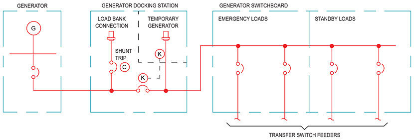
Common load bus configuration: The first way a docking station can be introduced into an electrical system is by connecting the load side of the docking station to the load side of the generator. In a practical application, this can be accomplished by providing a single feeder from the distribution point for the generator, which may be a panelboard or switchboard (Figure 1). This solution is ideal for retrofit applications, where the generator and emergency distribution system equipment are already installed. This configuration can also be ideal for site configurations where the docking station location is not near the permanent generator location. To comply with NEC 700.3(F), a mechanical or electrical interlock must be installed to prevent the inadvertent connection of two power sources. The simplest way to provide this interlock is with a mechanical key type locking mechanism, which is configured to require the generator circuit breaker to be in the open position before the temporary generator connectors can be accessed.
Figure 1: The common load bus configuration connects the docking station directly to a generator distribution panelboard.
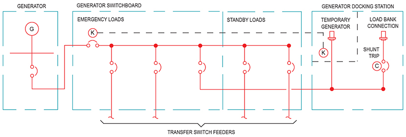
In-line configuration: For this configuration, the docking station is placed between the generator and the distribution equipment (Figure 2). One advantage of this configuration over the common load bus is it does not require a separate feeder from the distribution equipment, providing reduced material and labor costs. This configuration is ideal for situations where the docking station can be placed near the permanent generator location.
Figure 2: The in-line configuration places the docking station between the generator and the generator distribution panelboard.
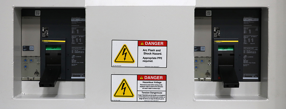
Particular attention should be paid to the quantity and location of circuit breakers, which are integral to the docking station, as well as the point the permanent generator conductors are terminated. In some single circuit breaker configurations, the conductors on the load side of the permanent generator circuit breaker remain energized when the temporary generator is connected. This creates a potentially dangerous situation, especially if the generator is undergoing maintenance and the technicians are not aware of this condition. The recommended solution is to specify a docking station circuit breaker configuration that fully isolates the generator conductors from the temporary generator source.
Load bank considerations
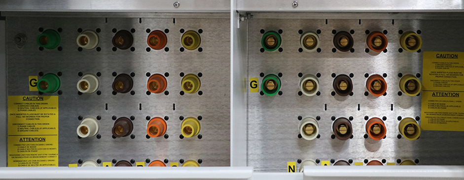
When a generator docking station is installed, a piece of equipment, which is permanently wired to the emergency power distribution equipment is now accessible at the exterior of the building. For project applications that warrant the frequent use of portable load banks, this presents a great opportunity to make load bank hook-ups quick and efficient. Docking stations are available in configurations designed for load banks only, but it is likely the design engineer or facility owner will also want the capability of connecting a temporary generator. In this situation, it is recommended a dual-purpose docking station be specified. A dual-purpose docking station contains male connectors for temporary generator cables and female connectors for portable load bank cables (Figure 3). The male connectors for the temporary generator can be placed behind a keyed door; this keyed lock can be part of the safety interlocking system designed to prevent the inadvertent energization of multiple power sources at the same time. The female connectors are available to allow a load bank to be connected.
Figure 3: ESL Dual purpose docking station connections for a load bank and temporary generator.
It is highly recommended a circuit breaker be provided for the load bank connections. This circuit breaker provides a convenient way to energize and de-energize the load bank connectors, but it also allows the user to automatically disconnect the load bank should a utility outage cause any of the transfer switches to transfer their load onto the generator bus. To successfully implement this safeguard against overloading the generator during load bank testing the load bank circuit breaker must have a shunt trip coil, which is wired so the coil is energized when any of the transfer switches close their engine start circuit contacts. When designing this shunt trip circuit, it is important to coordinate the voltage source designated for the shunt trip coil with the circuit breaker’s specifications provided by the docking station manufacturer.
Service entrance applications
Docking stations have applications beyond just emergency systems. Many facility owners recognize the value in having the option to bring in a larger temporary generator sized to power the entire facility. For this type of application, a docking station (or more appropriately a Manual Transfer Switch) can be installed between the main power transformer for the building and the main switchboard or distribution panel. This design allows a portable generator to take the place of the utility service in the event of a prolonged outage.
When designing a docking station (MTS) for a service entrance application, the design engineer should consider specifying a docking station with an integral circuit breaker. The addition of this circuit breaker offers multiple advantages such as:
Provides a safe and convenient location to disconnect utility power.
The temporary generator installer does not have to gain entry to the building to disconnect utility power.
The circuit breaker can replace the main overcurrent protective device often found in the main switchboard (Figure 4) (Note: this only applies for installations in which the docking station is located near where the conductors enter the building as required per NEC 225.32).
Figure 4: Insulated-case main circuit breakers with key interlock installed in an ESL service entrance docking station.
It is important to specify a mechanical interlock on the docking station; this mechanism prevents the temporary generator installer from gaining access to the terminations before opening the utility circuit breaker. It is also important to consider this point in the electrical system will often see high fault currents since it is so close to the utility transformer. Most manufacturers will be able to provide a 65kA short-circuit interrupting rating as part of their standard offering. If the available fault current exceeds 65kA, a 100kA rated docking station (MTS) must be specified. A 100kA rated docking station (MTS) may not be available from all manufacturers, so it is important to understand what manufacturers can meet this specification requirement should the application call for it.
When implementing a service entrance docking station, the design engineer and installers should pay particular attention to the grounding system connections. The usual methods of installing a main bonding jumper between the grounded service conductor and the equipment grounding bus still apply when installing a docking station. NEC article 250 requires this bonding jumper be installed at either the service transformer or the enclosure of the first disconnecting means, which would be the generator docking station in this case.
Fire pump installation requirements
Fire pump installations have specific requirements outlined in NEC article 695. When applying a generator docking station solution to a project with a fire pump backed up by a generator, special attention should be paid to the location of the fire pump disconnecting means.
A typical design strategy for serving a fire pump from a generator is to provide a dedicated circuit breaker on the generator set. Very often this is an ideal solution for powering a fire pump from the generator, as it allows the conductors to be kept outside of the building all the way from the generator to the fire pump room, therefore eliminating the need to use expensive two-hour fire rated cabling. However, the addition of a generator docking station in an in-line configuration introduces a new problem: the fire pump’s emergency power feeder will not be energized if a temporary generator is utilized while the permanent generator is switched off for maintenance or repair. This situation is the exact opposite of what the introduction of NEC 700.3(F) is trying to achieve. One possible solution to this problem is installing the fire pump disconnecting means directly adjacent to the docking station with the conductors tapped from the load bus of the docking station.
An alternate method for feeding the fire pump from the generator is providing a feeder from a common generator bus such as a distribution panelboard or switchboard. In this setup, the fire pump feeder overcurrent device will be energized when the docking station is powered from a temporary generator. However, depending on the location of the fire pump room, this situation may require the use of two-hour fire rated cabling if the feeder is to be routed within the building. The implications of putting the fire pump disconnecting means at a convenient location such as generator equipment should be evaluated to determine if the advantages outweigh any additional costs.
Engine start considerations
A code requirement that cannot be overlooked is the engine starting requirements for temporary emergency power sources. NEC 700.3(F)(2) references the same code article (NEC 700.12) that applies to permanently installed generators, which requires the generator to start and transfer the load within 10 seconds. To comply with this requirement, engine start wiring should be provided from the transfer switch generator start terminals to the docking station, as this will provide a convenient point for the temporary generator installer to access the start signal wiring.
Accessories for docking stations
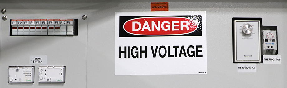
Docking stations have many optional accessories that should be considered for inclusion based on the application requirements. Common available accessories are listed below (Figure 5).
Figure 5: Typical docking station accessories (from left to right): Fuses, ERMS Switches, dehumidistat, and thermostat.
1. 2-wire auto start contacts:A set of posts that provides a convenient and readily accessible set of contacts for connecting the auto start signal from the building transfer switches to the temporary generator.
2. Convenience receptacles/shore power connections:Many temporary generators have separate power connections for jacket water heaters, space heaters, battery chargers and service receptacles. Receptacles can be provided integral to the docking station to keep all the connections in a single convenient location. Most temporary generator optional connections are 120V. These connections are typically only necessary for applications where the temporary generator may be sitting idle for a period of time.
3. Load shed receptacle:For applications where the docking station is serving as a connection point for a load bank, this feature will allow the load bank to automatically be shed if the utility power goes down during a load bank test.
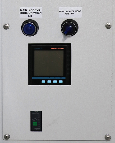
4. Utility indicator lights:Lights which illuminate when the utility voltage is present. This feature can be helpful for the contractors to confirm that utility has been restored before disconnecting the temporary generator (Figure 6).
5. Thermostat and strip heater: Prevents condensation accumulation inside the docking station cabinet.
6. Phase rotation monitor: This device helps the contractor verify the temporary generator phase rotation is correct before energizing the load. It should be noted that NEC 700.3(F) requires this accessory for docking stations serving emergency systems. Even in situations where a phase rotation monitor is not code required, it is recommended that this accessory be provided (Figure 6).
Figure 6: Phase rotation monitor and indicator lights.
How generator docking stations help
Adding a generator docking station can be a very useful solution for complying with current codes and improving system reliability during generator maintenance and repairs. However, the introduction of another system component can increase complexity, so it is critical that docking station installations receive a detailed engineering design to provide a safe and reliable system.
If you’re looking for assistance on specifying or designing a generator docking station, ESL can help! Contact our team now.